Fundamentals of Zener Diodes
Introduction to Special Purpose Diodes
Rectifier Diodes:
Commonly used for converting AC voltage to DC in power supplies.
Beyond Rectification:
Diodes serve in various applications beyond rectification.
Zener Diodes:
Optimized for breakdown properties.
Essential for voltage regulation in circuits.
Other Diodes Covered:
Optoelectronic Diodes (e.g., LEDs)
Schottky Diodes (known for low forward voltage drop)
Varactor Diodes (used for variable capacitance)
Additional special-purpose diodes for specific applications.
The Zener Diode
Operation:
Unlike small-signal and rectifier diodes, Zener diodes are designed to operate in the breakdown region.
Backbone of voltage regulators, maintaining a nearly constant load voltage despite fluctuations.
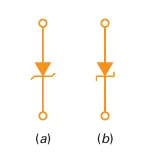
Schematic Symbol:
Two variations of Zener diode symbols resemble a “z” for "Zener."
Breakdown Voltages:
Vary from 2V to over 1000V, depending on doping levels.
I-V Characteristics of Zener Diode
Operating Regions:
Forward Region:
Conducts at \(\sim0.7~\mathrm{V}\), like a regular silicon diode.
Leakage Region:
Small reverse current between zero and breakdown.
Breakdown Region:
Sharp knee followed by a near-vertical increase in current.
Voltage stays approximately constant \((V_Z)\) in the breakdown region.
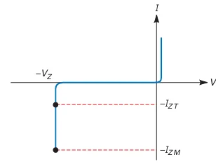
Safe Operation:
Maximum reverse current: \(I_{ZM}\).
Exceeding \(I_{ZM}\) leads to diode destruction.
A current-limiting resistor is essential to protect the diode.
Zener Resistance
Third Approximation of a Diode:
Forward voltage = Knee voltage + Voltage across bulk resistance
Reverse voltage = Breakdown voltage + Voltage across bulk (Zener) resistance
Zener Resistance:
Defined as the inverse slope of the I-V curve in the breakdown region.
More vertical breakdown region = smaller Zener resistance
Effect on Reverse Current:
Increase in reverse current leads to a slight increase in reverse voltage.
Typically, this voltage increase is only a few tenths of a volt.
Design Considerations:
Zener resistance matters in design but is often ignored in troubleshooting or preliminary analysis.
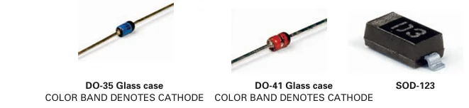
Visual Representation:
Fig. shows typical Zener diodes.
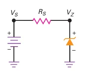
Zener Regulator
Constant Output Voltage:
Zener diode maintains a constant output voltage even as current changes.
Requires reverse bias for normal operation.
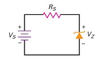
Operating Conditions:
Source voltage (\(V_s\)) must be greater than Zener breakdown voltage (\(V_Z\)).
A series resistor (\(R_s\)) is used to limit current and prevent burnout.
Voltage Measurement :
Measure voltage across \(R_s\) by taking readings at each end with respect to ground.
- Subtract voltages to find the voltage across the series resistor.
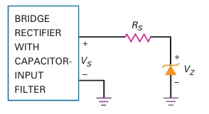
Zener Voltage Regulator :
A Zener regulator provides a DC output voltage that is less than the power supply output.
Commonly used for voltage regulation in circuits.
Zener Regulator – Current Calculation
Current through Series Resistor:
Voltage across the series resistor (\(R_s\)) = Source voltage \((V_S)\) - Zener voltage \((V_Z)\).
Current through the resistor:
\(I_s\) is equal to the Zener current since the circuit is in series.
Important: \(I_s\) must be less than \(I_{ZM}\) to prevent damage.
Ideal Zener Diode Approximation
Ideal Zener Diode:
For troubleshooting and analysis, the breakdown region can be approximated as vertical.
Voltage is constant even with varying current (ignoring Zener resistance).
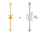
Circuit Simplification:
A Zener diode in the breakdown region acts like a constant voltage source \((V_Z)\) .
This simplifies analysis as you can mentally replace the Zener diode with a battery of voltage \(V_Z\).
Problem-1
- The breakdown voltage of the zener diode shown in the Fig. is 10
V. What are the minimum and maximum zener currents?
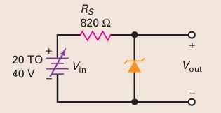
Applied voltage \(20-40~\mathrm{V}\) (vary)
Zener diode replace with a battery of \(10~\mathrm{V} \Rightarrow\) output voltage is \(10~\mathrm{V}\) (fixed)
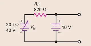
Output Voltage Stability: Held constant at 10 V.
Source Voltage Variation: Changes from 20 V to 40 V.
Zener Diode Behavior:
Increased source voltage leads to more Zener current.
Output voltage remains rock-solid at 10 V.
Conclusion: Zener diode ensures stable output voltage despite changes in input voltage.
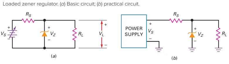
Loaded Zener Regulator
Operation:
Zener diode holds load voltage constant in the breakdown region.
Load voltage \((V_L)\) stays fixed at the Zener voltage \((V_Z)\) despite changes in source voltage or load resistance.
Voltage Divider & Thevenin Voltage:
Thevenin voltage (\(V_{TH}\)) facing the diode:
Breakdown occurs only if \(V_{TH} > V_Z\).
Current Calculations in Loaded Zener Regulator
- \[I_S = \frac{V_S - V_Z}{R_S}\]\((I_S)\)Series Current
\(I_S\) remains the same whether or not the load resistor is connected.
Load Voltage \((V_L)\):
Ideally, \(V_L = V_Z\) because the load resistor is in parallel with the Zener diode.
- \[I_L = \frac{V_L}{R_L}\]\((IL)\)Load Current
Zener Current Calculation
- \[I_S = I_Z + I_L\]\((I_S)\)Total Current
The sum of Zener current and load current equals the series current (Kirchhoff’s Current Law).
- \[I_Z = I_S - I_L\]\((I_Z)\)Zener Current
\(I_Z\) no longer equals \(I_S\) as in an unloaded regulator; it’s reduced by the load current.
Summary of Loaded Zener Regulator Analysis
- \[I_S = \frac{V_S - V_Z}{R_S}\]\((I_S)\)Calculate Series Current
- \[V_L = V_Z\]\((V_L)\)Determine Load Voltage
- \[I_L = \frac{V_L}{R_L}\]\((I_L)\)Calculate Load Current
- \[I_Z = I_S - I_L\]\((I_Z)\)Find Zener Current