ELECTROMECHANICAL ENERGY CONVERSION
A device (machine) that converts energy from electrical to mechanical form or from mechanical to electrical form is called an electro-mechanical energy conversion device.
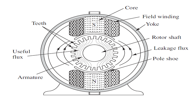
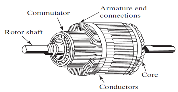
A DC machine (generator or motor) is an electromechanical energy conversion device.
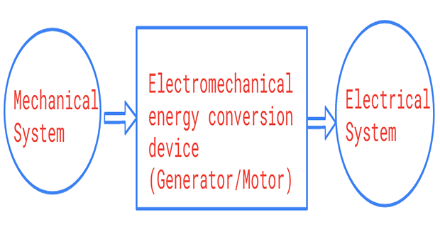
DC Generator: convert mechanical power (\(T\omega\)) into DC electrical power (\(EI\))
DC Motor: convert electrical power into mechanical power
The same electromechanical device is capable of operating either as a motor or generator depending upon whether the input power.
Thus, the motor and generator actions are reversible.