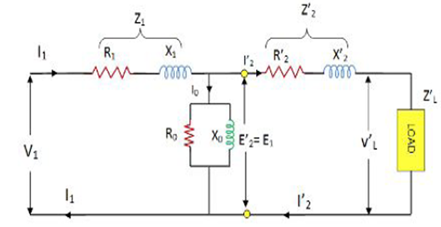
Solution-1
 \[\begin{aligned}
K &=230 / 2300=1 / 10 \\
Z_{L}&=0.387+j 0.29 \\
\mathrm{Z}_{L}^{\prime} &=\mathrm{Z}_{L} / K^{2}\\
&=100(0.387+j 0.29)=38.7+j 29=48.4 \angle 36.8^{\circ} \\
\end{aligned}\]
The parameters of a \(2300 / 230 \mathrm{~V}, 50 \mathrm{~Hz}\) transformer are given below: \[\begin{aligned} R_1 & = 0.286~\Omega ~~ R_2^{\prime} = 0.319~\Omega ~~ R_0 = 250~\Omega \\ X_1 & = 0.73~\Omega ~~ X_2^{\prime} = 0.73~\Omega ~~ X_0 = 1250~\Omega \end{aligned}\] The secondary load impedance \(z_{L}=0.387+j 0.29\).
Using the exact equivalent circuit with normal voltage across the primary, determine
input power factor,
power input,
power output,
primary and secondary Cu loss,
Efficiency and regulation
 \[\begin{aligned}
K &=230 / 2300=1 / 10 \\
Z_{L}&=0.387+j 0.29 \\
\mathrm{Z}_{L}^{\prime} &=\mathrm{Z}_{L} / K^{2}\\
&=100(0.387+j 0.29)=38.7+j 29=48.4 \angle 36.8^{\circ} \\
\end{aligned}\]
\[\begin{aligned} \mathrm{Z}_{2}^{\prime}+\mathrm{Z}_{L}^{\prime} &=(38.7+0.319)+j(29+0.73)\\ &=39.02+\mathrm{j} 29.73=49.0 \angle 37.3^{\circ} \\ Y_{m} &=(0.004-j 0.0008) \\ Z_{m}&=1 / \mathrm{Y}_{m}=240+j 48=245 \angle 11.3^{\circ} \\ \mathrm{Z}_{m}+\left(Z_{2}^{\prime}+Z_{L}{ }^{\prime}\right) &=(240+j 48)+(39+j 29.7)=290 \angle 15.6^{\circ} \end{aligned}\]
\[\begin{aligned} I_{1} &=\frac{V_{1}}{Z_{1}+\frac{Z_{m}\left(Z_{2}^{\prime}+Z_{L}\right)}{Z_{m}\left(Z_{2}^{\prime}+Z_{L}^{\prime}\right)}}=\left[\frac{2300 \angle 0^{\circ}}{0.286+j 0.73+41.4 \angle 33^{\circ}}\right] \\ &=\frac{2300 \angle 0^{\circ}}{42 \angle 33.7^{\circ}}=54.8 \angle-33.7^{\circ} \\ I_{2}^{\prime} &=I_{1} \times \frac{Z_{m}}{\left(Z_{2}^{\prime}+Z_{L}^{\prime}\right)+Z_{m}}=54.8 \angle-33.7^{\circ} \times \frac{245 \angle 11.3^{\circ}}{290 \angle 15.6^{\circ}} \\ &=54.8 \angle-33.7^{\circ} \times 0.845 \angle-4.3^{\circ}=46.2 \angle-38^{\circ} \\ I_{0} &=I_{1} \times \frac{\left(Z_{2}^{\prime}+Z_{L}^{\prime}\right)}{Z_{m}+\left(Z_{2}^{\circ}+Z_{L}\right)}=54.8 \angle-33.7^{\circ} \times \frac{49 \angle 37.3^{\circ}}{290 \angle 15.6^{\circ}} \\ &=54.8 \angle-33.7^{\circ} \times 0.169 \angle 21.7^{\circ}=9.26 \angle-12^{\circ} \end{aligned}\]
\[\begin{aligned} \text { Input power factor } &=\cos 33.7^{\circ}=0.832 \text { lagging }\\ \text { Power input } & =V_{1} I_{1} \cos \phi_{1}=2300 \times 54.8 \times 0.832=105 \mathrm{~kW} \\ \text { Power output } & =46.2^{2} \times 38.7=82.7 \mathrm{~kW} \\ \text { Primary Cu loss } & =54.8^{2} \times 0.286=860 \mathrm{~W} \\ \text { Secondary Cu loss } & =46.2^{2} \times 0.319=680 \mathrm{~W} \\ \text { Core loss } & =9.26^{2} \times 240=20.6 \mathrm{~kW} \\ \eta & =(82.7 / 105) \times 100=78.8 \% \\ V_{2}^{\prime}&=I_{2}^{\prime} Z_{L}^{\prime}=46.2 \times 48.4=2,240 \mathrm{~V}\\ \text { Regulation }&=\frac{2300-2240}{2240} \times 100=2.7 \% \end{aligned}\]
In no-load test of single-phase transformer, the following test data were obtained:
\[\begin{aligned} \text{Primary voltage}: & 220 \mathrm{~V} \quad \text{Secondary voltage}: 110 \mathrm{~V}\\ \text{Primary curren}t: & 0.5 \mathrm{~A} \quad \text{Power input}: 30 \mathrm{~W} \end{aligned}\]
Find the following
The turns ratio
the magnetizing component of no-load current
working (or loss) component
the iron loss
Given: Resistance of the primary winding \(=0.6\) ohm
\[\begin{aligned} \text{Turn ratio},~ N_{1} / N_{2}&=220 / 110=2 \\ W&=V_{1} I_{0} \cos \phi_{0}\\ \Rightarrow \cos \phi_{0} &=30 / 220 \times 0.5=0.273 \\ \sin \phi_{0}&=0.962 \\ I_{\mu} &=I_{0} \sin \phi_{0}=0.5 \times 0.962=0.48 \mathrm{~A} \\ I_{w}&=I_{0} \cos \phi_{0}=0.5 \times 0.273=0.1365 \mathrm{~A} \\ \text{Primary Cu loss} &=I_{0}^{2} R_{1}=0.5^{2} \times 0.6=0.15 \mathrm{~W} \\ \text{Iron loss} &=30-0.15=29.85 \mathrm{~W} \end{aligned}\]
Obtain the equivalent circuit parameters of a \(200 / 400 \mathrm{~V}, 50 \mathrm{~Hz}, 1\) -phase transformer from the following test data:
\[\begin{aligned} \text{OC Test}:~~& 200 \mathrm{~V}~~ 0.7 \mathrm{~A}~~ 70 \mathrm{~W} --\mathrm{LV side} \\ \text{SC Test}: ~~& 15 \mathrm{~V} ~~ 10 \mathrm{~A} ~~ 85 \mathrm{~W}--\mathrm{HV side} \end{aligned}\]
Calculate the secondary voltage when delivering \(5 \mathrm{KW}\) at \(0.8 \mathrm{pf}\) lagging, the primary voltage being \(200 \mathrm{~V}\)
From O.C.Test \[\begin{aligned}
V_{1} I_{0} \cos \phi_{0} &=W_{0} \\
200 \times 0.7 \times \cos \phi_{0} &=70 \\
\cos \phi_{0} &=0.5 \\
\sin \phi_{0}&=0.866 \\
I_{w} &=I_{0} \cos \phi_{0}\\
&=0.7 \times 0.5=0.35 \mathrm{~A} \\
I_{\mu} &=I_{0} \sin \phi_{0}\\
&=0.7 \times 0.866\\
&=0.606 \mathrm{~A} \\
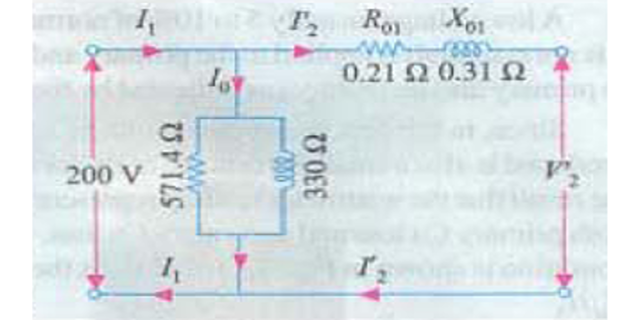
R_{0} &=V_{1} / I_{\mathrm{w}}=200 / 0.35=571.4 \Omega \\
X_{0} &=V_{1} / I_{\mathrm{u}}=200 / 0.606=330 \Omega
\end{aligned}\]

From S.C. Test : instruments have been placed in the secondary i.e. high-voltage winding whereas the low-voltage winding i.e, primary has been short-circuited. \[\begin{aligned} Z_{02} &=V_{sc} / I_{2}=15 / 10=1.5 \Omega \\ K&=400 / 200=2 \\ Z_{01} &=Z_{02} / K^{2}=1.5 / 4=0.375 \Omega \\ I_{2}^{2} R_{02} &=W \\ \Rightarrow R_{02}&= W/I_{2}^{2} = 85 / 100=0.85 \Omega \\ R_{01} &=R_{02} / K^{2}=0.85 / 4=0.21 \Omega \\ X_{01} &=\sqrt{Z_{01}^{2}-R_{01}^{2}}=\sqrt{0.375^{2}-0.21^{2}}=0.31 \Omega \end{aligned}\] \[\begin{aligned} \text { Output } \mathrm{kVA}&=5 / 0.8 \\ \text { Output current } I_{2}&=5000 / 0.8 \times 400=15.6 \mathrm{~A} \end{aligned}\]
Total transformer drop as referred to secondary \[\begin{aligned} &=I_{2}\left(R_{02} \cos \phi_{2}+X_{02} \sin \phi_{2}\right)\\ &=15.6(0.85 \times 0.8+1.24 \times 0.6)=22.2 \mathrm{~V} \\ V_{2}&=400-22.2=377.8 \mathrm{~V} \end{aligned}\]