Demonstrative Video
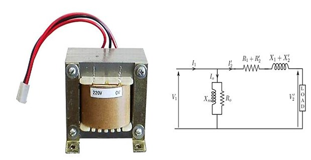
The performance of a transformer can be calculated on the basis of its equivalent circuit which contains four parameters (as referred to primary)
the equivalent resistance \(R_{01}\)
the equivalent leakage reactance \(X_{01}\)
the core loss conductance \(G_0\) or resistance \(R_0\)
the magnetizing susceptance \(B_0\) or reactance \(X_0\)
These constants or parameters can be determined by two tests:
open-circuit tests
short-circuit tests
Tests also determine the voltage regulation and efficiency.
Tests are very economical and convenient, because they furnish the required information without actually loading the transformer
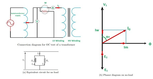
The shunt branch parameters are determined by performing this test
The core loss and the magnetizing current depend on applied voltage only and are practically unaltered by the load current
Hence to get these parameters, Rated voltage is supplied generally to LV winding keeping HV open
\(I_0\) is very small as compared to \(I_{FL}\) the loss in \(R_1\) is neglected
Thus \(W_0\) drawn from source is dissipated as heat in the core
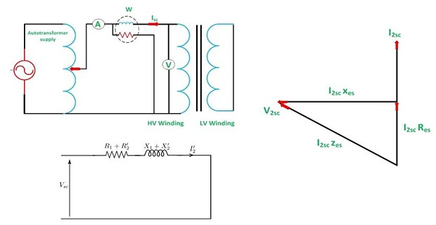
Input voltage is reduced to a small fraction of rated value and secondary terminals are short-circuited.
A current will circulate in the secondary winding.
Since a small fraction of rated voltage is applied to the primary winding, the flux in the core and hence the core loss is very small.
Hence, the power input on short circuit is dissipated as heat in the winding
Since, the applied voltage is very small (may be of the order of 5-8%), the magnetizing branch can now be eliminated from the equivalent circuit.
Copper losses \((I^2R)\) depends on current which passing through transformer winding
Iron losses or core losses or Insulation losses depends on Voltage.
Total losses depends on voltage (V) and current (I) which expressed in Volt ampere (VA) and not on the load power factor (p.f).
Hence, the transformer rating may be expressed in VA or kVA, not in W or kW
Moreover manufactures design a transformer with no idea which kind of load will be connected to the transformer
The load may be resistive (R), inductive (L), capacitve (C) or mixed load (R, L and C).
Its mean, there would be different power factor (p.f) at the secondary (load) side on different kind of connected loads depends on R, L and C.
- The percentage of voltage difference between no load and full load voltages of a transformer with respect to its full load voltage\[\mbox{voltage regulation}(\%)=\dfrac{E_{2}-V_{2}}{V_{2}}\times100\]
At no load, the secondary terminal voltage is \(E_2\)
At full load, rated current \(I_2\) flows through the secondary circuit and voltage drop comes into picture.
At this situation, primary winding will also draw equivalent full load current from source.
The voltage drop due to the secondary impedance is \(I_2Z_2\)
- \(-\)\(+\)In general, voltage regulation is given by\[\mbox{voltage regulation}(\%) = \dfrac{I_2R_2\cos\theta_2 \pm I_2X_2\sin\theta_2 }{V_2}\]
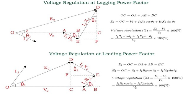
Voltage Regulation