Exp-1: No-load and Load Test on DC Shunt Generator
Demonstrative Video
Theoretical Explanation
Experiment
OBJECTIVE FOR NO LOAD TEST
- To obtained the magnetization characteristic at rated speed
- Predetermine the O.C.C at 1000 rpm
- Determine the critical field resistance at rated speed
- Determine critical speed of the given dc shunt generator
Name Plate Details
|
NAME PLATE DETAILS OF DC SHUNT MOTOR & GENERATOR |
||
|
|
DC Motor |
DC Generator |
|
KW Rating |
3.5 KW |
3.5 KW |
|
Voltage |
220 V |
220 V |
|
Current |
18.6 A |
16 A |
|
Speed |
1500 RPM |
1500 RPM |
|
Excitation current |
0.95 A |
0.9 A |
|
Winding type |
Shunt |
Shunt |
|
|
Ra : 0 .6 Ω , Rsh : 187 Ω |
Ra : 1.1 Ω , Rshg : 183 Ω |
|
Thyristor Controlled DC drive: 0-250 V DC for 5 HP DC Motor |
||
APPARATUS REQUIRED
|
S.No. |
Name of the Equipment |
Range |
Quantity |
Type |
|
1. |
Voltmeter |
300 V |
2 Nos |
Digital |
|
2. |
Ammeter |
20 A |
2 Nos |
Digital |
|
3. |
Rheostat |
360Ω/1.6A |
2 Nos |
Coil |
|
4. |
Resistive Load |
230 V/20 A |
1 No |
Coil |
|
5. |
Tachometer |
2000 Rpm |
1 No |
Digital |
NO LOAD TEST ON DC SHUNT GENERATOR
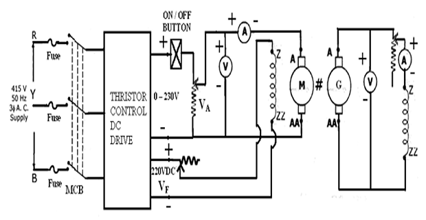
CIRCUIT DIAGRAM FOR NO LOAD TEST:
Introduction
- The EMF induced in a DC machine is proportional to the flux per pole, the number of conductors and speed. This EMF depends on speed and flux. As the flux increases the EMF increases beyond a point the flux gets saturated. The B-H curve of the core depicts the magnetization curve of the machine. $$ E_a = \dfrac{Z \cdot \phi \cdot n P}{60} $$ where \begin{aligned} Z &– \text{no. of armature conductors}\\ \phi & - \text{Flux/pole} \\ N & - \text{Speed in rpm} \\ P &- \text{No. of poles}\\ A& – \text{Number of parallel paths (=P for lap & =2 for wave winding)} \end{aligned}
- For a given machine Z, P and A are constant. Therefore equation can be written as $$ E_a = k \cdot \phi \cdot N $$
- For a given dc shunt generator we can write $$ V = E_a - I_a \cdot R_a $$
Where \( V\) , \(I_a \) and \( R_a\) are the terminal voltage, armature current and armature resistance of a dc generator respectively and n is the speed of the generator.
- At no load \( I_a\) is negligible. Therefore equation can be written as $$ V = V_0 = k \cdot \phi \cdot n $$
Here, n is speed which is kept constant at rated value. Therefore
$$ V = k_1 \cdot \phi $$The flux per pole \(\phi \) is a function of \(I_f \) , the field current. The no-load voltage \(V_0\) being proportional to \( \phi\) represent magnetization characteristic, as \( V_0\) is the no-load voltage.
- The O.C.C or the magnetization characteristic or no load characteristics is a curve showing the relationship between the emf generated at no load and the shunt field current (\( V~\text{and}~I_f\) ) at a given speed.
- Even when the field current is zero there is some residual magnetism present in the poles. Hence there is a small voltage generated even at zero field current, which is called the residual voltage.
- As \( I_f\) is increased, \(V \) also increases and the curve traced is almost a straight line. As \( I_f\) is further increased, the poles start getting saturated, the straight line relation no longer holds good and the curve becomes almost flat
- The magnetization characteristic is obtained by controlling the \(I_f \) of the generator with the help of the rheostat and thus the flux. It varies from zero and is measured on an ammeter connected in the circuit diagram
- As \(I_f \) is varied, \( \phi\) changes and hence induced e.m.f. \( E_0\) or \( V_0\) also varies. It is measured on voltmeter connected across armature of generator
- No load is connected to the machine, hence characteristics are also called no load characteristics which is graph of \( E_0\) against \( I_f\) . As \(I_f \) increases, flux \( \phi\) increases and \( E_0\) increases
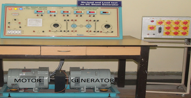
LAB SET-UP
PRECAUTIONS
- Motor field rheostat must be kept in minimum resistance position.
- Potential divider must be kept in minimum potential position.
- Starter arm must be in OFF position.
Connections
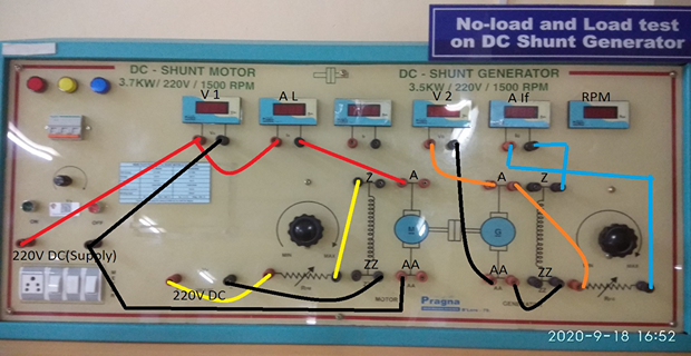
- Supply Positive to Voltmeter Terminal (Red)
- Voltmeter(1) Terminal (Red) to Ammeter(1) Terminal (Red)
- Ammeter(1) Terminal (Black) to Motor A
- Voltmeter(2) Terminal (Red) to Generator A
- Voltmeter(2) Terminal (Black) to Generator AA
- Generator A to Generator Field Rheostat Terminal (Red)
- Ammeter(2) Terminal (Red) to Generator Field Rheostat Terminal (Black)
- Ammeter(2) Terminal (Black) to Generator Z
- Generator AA to Generator ZZ
- Supply Negative to Voltmeter Terminal (Black)
- Supply Negative to Motor AA
- 220V DC Terminal (Red) to Motor Field Rheostat Terminal (Red)
- Motor Field Rheostat Terminal (Black) to Motor Z
- 220V DC Terminal (Black) to Motor ZZ
PROCEDURE
- Connect the circuit as shown in the Fig.1
- Motor field rheostat must be kept in minimum resistance position, armature potentiometer knob ‘VA’ at minimum voltage position and generator field rheostat at maximum position.
- Switch on the MCB and push ‘ON’ button.
- Slowly vary the Armature potentiometer knob ‘VA” such that voltage applied to D.C. motor is 220 volts.
- Adjusting the motor field rheostat, bring the motor-generator to rated speed i.e., 1500 rpm.
- Increase the excitation of the generator in steps by adjusting the generator field rheostat and note down the inducted emf and generator field current readings.
- Take the readings up to 20% of the rated voltage (220V) of the generator.
- Decrease the excitation of the field current to zero by adjusting the generator field rheostat.
- Take down the readings in the reverse operation.
- Observe the precautions and switch off the supply
- Measure the field resistance Rsh of the generator using a multimeter.
- Compute the OCC at 1000 rpm and plot the characteristic on the same graph.
- Find critical resistance and critical speed.
OBSERVATION TABLE
Speed of the Generator: 1500 r.p.m.
|
S.No. |
1 |
2 |
3 |
4 |
5 |
6 |
7 |
8 |
9 |
10 |
11 |
12 |
13 |
14 |
15 |
|
If (A) |
|
|
|
|
|
|
|
|
|
|
|
|
|
|
|
|
Eo (V) Forward Direction |
|
|
|
|
|
|
|
|
|
|
|
|
|
|
|
|
Eo (V) Reverse Direction |
|
|
|
|
|
|
|
|
|
|
|
|
|
|
|
MODEL GRAPH

CRITICAL FIELD RESISTANCE & SPEED
CRITICAL RESISTANCE:
- It is that value of resistance in the field circuit at which the generator will just excite (or voltage build up begins). If the field resistance is higher, the machine will fail to build up voltage. It is given by the slope of the tangent drawn to the linear portion of the magnetization curve from the origin.
- It can be obtained by plotting the OCC and drawing a line which is tangential to the linear portion of the OCC.
From the graph OX is the tangent and the critical field resistance, $$ R_c = \dfrac{AC}{AB} $$
CRITICAL SPEED:
- It is that speed for which the given shunt field resistance becomes the critical field resistance. Critical field resistance is obtained by plotting the OCC and determining the slope of the tangent to the linear position of the curve from the origin. While drawing the tangent, the initial position of the OCC is neglected.
OY is the shunt field resistance line and the Critical speed is, $$ N_c = \dfrac{YZ}{XZ} \times \text{Rated Speed} $$
Rated speed is the speed at which the OCC is obtained.
RESULT & QUESTIONS
RESULT: Hence critical field resistance & critical speed of DC Shunt Generator is found using its open circuit characteristics.
QUESTIONS:
1. What is the need for starter in a d.c motor?
2. How does a 3-point starter function?
3. Why is Rheostat in motor field kept in minimum position at starting?
4. Why is Rheostat in generator field kept in maximum position at start up?
5. What is residual voltage? How is it measured?
6. What are the conditions necessary for voltage build up in a d.c shunt generator?
7. Explain the shape of the O.C.C.
LOAD TEST ON DC SHUNT GENERATOR
OBJECTIVE FOR LOAD TEST:
To obtain the External Characteristics and Internal Characteristics of a dc shunt generator.
INTRODUCTION:
Load characteristics of the machine can be broadly classified into,
- External characteristics
- Internal Characteristics
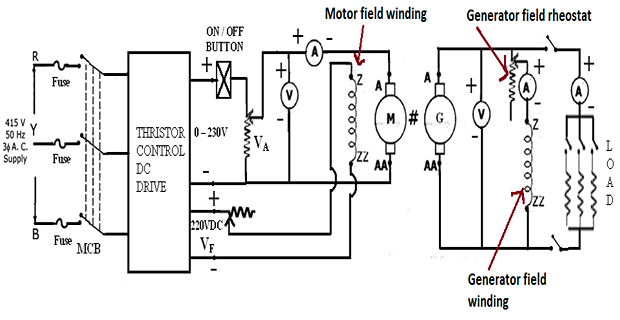
Use the circuit diagram shown, the field resistance of the generator adjusted to obtain the desired no – load voltage can be obtained. The external characteristic of the generator can then be obtained from load test. Speed is to be kept constant.
THEORY:
- Ideally the induced e.m.f. is not dependent on the load current IL, or armature current Ia.
- But as load current increases, the armature current Ia increases to supply load demand.
- As Ia increase, armature flux increases.
- Due to the armature reaction, main flux gets linked with the armature conductors. This reduces the induced e.m.f.
- The internal and external characteristic of the given DC shunt generator are obtained from this test.
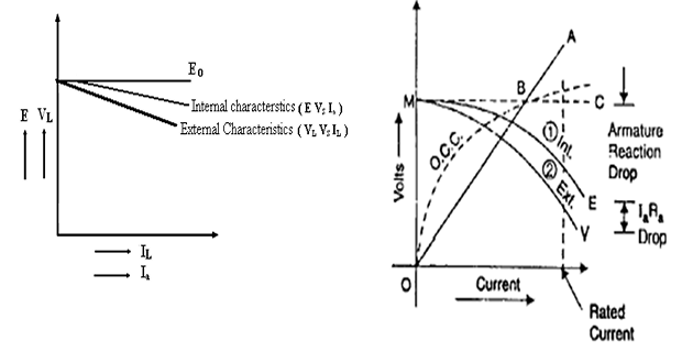
- The internal characteristic is obtained after obtaining the external characteristic from the load test and subtracting the armature resistance drop IaRa.
External Characteristics(VL vs IL):
- It is a curve showing the variation in terminal voltage of the generator as the load on the generator is increased. The characteristics are as shown in the model graph. At no load, the terminal voltage of the generator is at its rated value. As the load current is increased the terminal voltage drops. The drop in terminal voltage is due to the following reasons.
1. For a generator V = Eg - IaRa, as the load current increases, Ia increases, IaRa drop increases, thus decreasing the terminal voltage V.
2. As the load current increases, Ia increases, armature reaction effect also increases. Due to demagnetizing effect of armature reaction, the induced emf Eg decreases, thereby decreasing V.
3. Due to reasons (1) and (2), the terminal voltage decreases, which in turn reduces the field current If / Ish, thereby decreasing Eg causing further decrease in V.
Internal Characteristics(Eg vs Ia):
- It is a plot of the internally generated emf (Eg) and armature current (Ia). It is a curve similar to the external characteristics and lies above it as shown in model graph.
Eg = VL + IaRa
Ia = IL + If
CIRCUIT DIAGRAM FOR LOAD TEST:
CONNECTION:
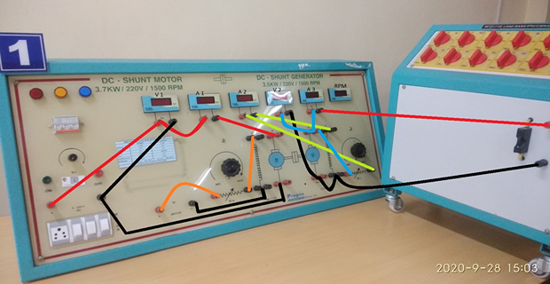
- Supply Positive to Voltmeter Terminal (Red)
- Voltmeter(1) Terminal (Red) to Ammeter(1) Terminal (Red)
- Ammeter(1) Terminal (Black) to Motor A
- Voltmeter(2) Terminal (Red) to Generator A
- Voltmeter(2) Terminal (Black) to Generator AA
- Generator A to Generator Field Rheostat Terminal (Red)
- Ammeter(2) Terminal (Red) to Generator Field Rheostat Terminal (Black)
- Ammeter(2) Terminal (Black) to Generator Z
- Generator A to Ammeter(3) Terminal (Red)
- Ammeter(3) Terminal (Black) to Resistive Load Terminal (Red)
- Generator AA to Generator ZZ
- Generator ZZ to Resistive Load Terminal (Black)
- Supply Negative to Voltmeter Terminal (Black)
- Supply Negative to Motor AA
- 220V DC Terminal (Red) to Motor Field Rheostat Terminal (Red)
- Motor Field Rheostat Terminal (Black) to Motor Z
- 220V DC Terminal (Black) to Motor ZZ
PROCEDURE
- Connect the circuit as shown in the Fig.
- Motor field rheostat must be kept in minimum resistance position, Armature potentiometer knob ‘VA’ at minimum position and generator field rheostat at maximum position.
- Switch on the MCB and Push ‘ON’ button.
- Slowly vary the Armature potentiometer knob ‘VA” such that voltage applied to D.C. motor armature(A & AA) is 220 volts.
- Adjusting the motor field rheostat to bring the motor-generator to rated speed i.e., 1500 rpm.
- By varying the field rheostat of generator, increase the output voltage of generator to rated value i.e., 220 V.
- Switch on the resistive load. Apply in step: at every step change in load and ensure speed is at rated value 1500 rpm (this is done using Motor field rheostat). Measure load voltage (VL), Load current (IL), Generator field current (IF). Ensure the load current of the generator is within the rated current of generator i.e., 16 Amps OR not exceeding the rated current of Motor.
- Gradually decreased the load current to zero and decrease the excitation of the field current to zero by adjusting the Generator field rheostat.
- Minimise the field resistance of Motor and switch OFF the supply.
- Measure the Armature resistance Ra of the generator using a multimeter.
- Plot the graphs for internal and external characteristics.
OBSERVATION TABLE:
|
S. No.
|
VL |
IL |
If |
Ia= IL+ If
|
E = VL+Ia Ra |
N =1500 rpm (constant) |
|
1 |
|
|
|
|
|
|
|
2 |
|
|
|
|
|
|
|
3 |
|
|
|
|
|
|
|
4 |
|
|
|
|
|
|
|
5 |
|
|
|
|
|
|
MODEL GRAPH
PRECAUTIONS
- Motor field rheostat must be kept in minimum resistance position.
- Potential divider must be kept in minimum potential position.
- Starter arm must be in OFF position.
Before starting the Machine:
Result:
The load characteristics of the shunt generator are obtained.
QUESTIONS
-
Why does the terminal voltage of a generator decrease with increase in load?
-
How are the meter ratings selected for this experiment?
-
What are the different losses in a DC generator?
-
What is the condition for maximum efficiency in a DC machine?
-
What is armature reaction? How does it affect the functioning of the machine?