Solved Problems on Reactance Diagrams
Problem-1
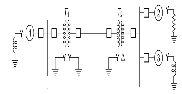
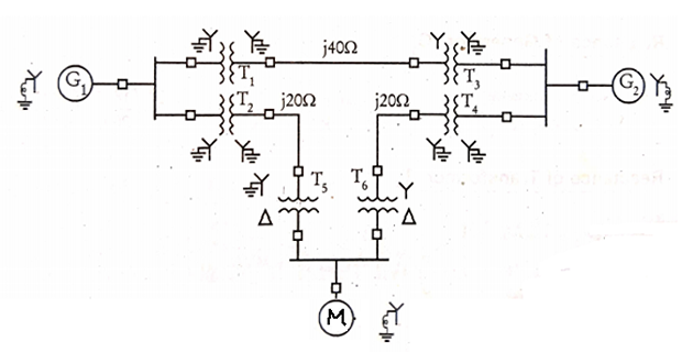
Consider the following 50-Hz PS SLD. The system ratings are:
Solution-1
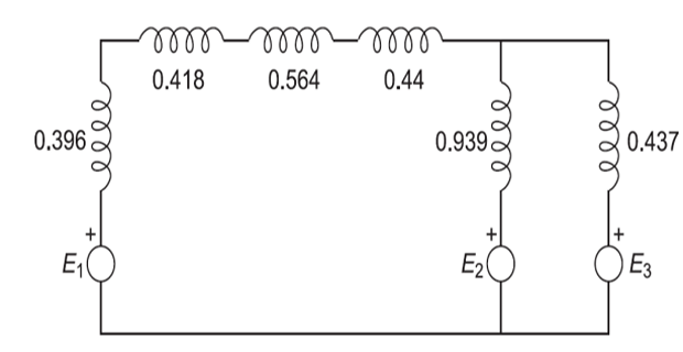
| Transmission Line: | \(\dfrac{20.5\times30}{33^{2}}=0.564\) |
| Transformer-1: | \(\dfrac{15.2\times30}{33^{2}}=0.418\) |
| Transformer-2: | \(\dfrac{16\times30}{33^{2}}=0.44\) |
| Generator-1: | \(\dfrac{1.6\times30}{11^{2}}=0.396\) |
| Generator-2: | \(\dfrac{1.2\times30}{6.2^{2}}=0.936\) |
| Generator-3: | \(\dfrac{0.56\times30}{6.2^{2}}=0.437\) |
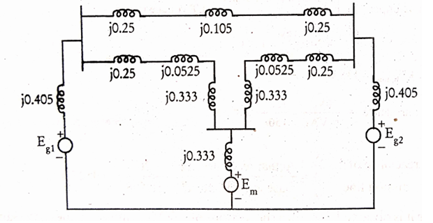
Reactance diagram of the given system:
Problem-2
Draw the reactance diagram choosing a base of 50 MVA, 138 kV in the 40 \(\Omega\) line
| Generator-G1: | 20 MVA | 18 kV | \(X''=20\%\) |
| Generator-G2: | 20 MVA | 18 kV | \(X''=20\%\) |
| Syn. Motor: | 30 MVA | 13.8 kV | \(X''=20\%\) |
| \(3\phi\) Y-T TF | 20 MVA | 138/20 kV | \(X''=10\%\) |
| \(3\phi\) Y-\(\Delta\) TF | 15 MVA | 138/13.8 kV | \(X''=10\%\) |
Solution-2
\(MVA_{b,new} = 50\) MVA
\(kV_{b,new} = 138\) kV
Reactance of \(j40~\Omega\) TL
\(Z_b = \dfrac{kV_{b,new}^2}{MVA_{b,new}} = \dfrac{138^2}{50} = 380.88~\Omega\)
- \[\begin{aligned} \left.\begin{array}{l}\text { p.u. reactance of } \\ 40 \Omega \text { TL }\end{array}\right\}&=\dfrac{\text { Actual reactance, } \Omega}{\text { Base impedance, } \Omega}\\ &=\dfrac{40}{380.88}=0.105 \mathrm{p} \cdot \mathrm{u} \end{aligned}\]
Reactance of Transformer T1
Reactance of Generator G1
\[\begin{aligned} \left.\begin{array}{l} \text { New p.u. } \\ \text{reactance} ~ G_{1} \end{array}\right\}&=X_{p u, \text { old }} \times\left(\frac{k V_{b, \text { old }}}{k V_{b, n e w}}\right)^{2} \times\left(\frac{M V A_{b, new}}{M V A_{b, \text { old }}}\right)\\ &=0.2 \times\left(\frac{18}{20}\right)^{2} \times\left(\frac{50}{20}\right)\\ &=0.405 \text { p.u. } \end{aligned}\]Reactance of Transformer T2
\[\begin{aligned} \left.\begin{array}{l} \text { New p.u. } \\ \text{reactance} ~ T_{2} \end{array}\right\}&=0.1 \times\left(\frac{20}{20}\right)^{2} \times\left(\frac{50}{20}\right)=0.25 \mathrm{p} \cdot \mathrm{u} \end{aligned}\]
Reactance of \(j20~\Omega\) TL
\[\begin{aligned} \left.\begin{array}{l} \text { Base kV on } \\ \text{HT side of} ~ T_{2} \end{array}\right\}&= \text{Base kV on LT side} \times \dfrac{\text{HT voltage rating}}{\text{LT voltage rating}} \\ & = 20 \times \dfrac{138}{20} = 138~kV\\ kV_{b,new} & = 138~kV\\ Z_b & = \dfrac{kV_b^2}{MVA_b} = \dfrac{138^2}{50} = 380.88~\Omega \\ \text{p.u reactance} & = \dfrac{\text{Actual reactance}~\Omega}{\text{Base impedance}~\Omega}\\ & = \dfrac{20}{380.88} = 0.0525 p.u. \end{aligned}\]Observe: both sections of j20 \(\Omega\) TL have same values of reactance and base k.V’s. Hence, their p.u. reactance will be same.
Reactance of TF \(T_5\)
\[\begin{aligned} \text { p.u. reactance } &=0.1 \times\left(\frac{138}{138}\right)^{2} \times\left(\frac{50}{15}\right)=0.333 \mathrm{p} . \mathrm{u} \end{aligned}\]- Reactance of Syn. Motor\[ \begin{aligned} \left.\begin{array}{l} KV_b \text { on } \\ \text{LT side}~ \mathrm{T}_{2} \end{array}\right\}&=\text { Base } \mathrm{kV} \text { on } \mathrm{HT} \text { side } \times \frac{\text { LT voltage rating }}{\text { HT voltage rating }}\\ &=138 \times \frac{13.8}{138}=13.8 \mathrm{kV}\\ \left.\begin{array}{l} \text { New p.u. reactance } \\ \text { of syn. motor } \end{array}\right\}&=X_{\mathrm{pu}, \text { old }} \times\left(\frac{\mathrm{kV}_{\mathrm{b}, \mathrm{old}}}{\mathrm{kV}_{\mathrm{b}, \mathrm{ncw}}}\right)^{2} \times\left(\frac{\mathrm{MVA}_{\mathrm{b}, \mathrm{new}}}{\left.\mathrm{MVA}_{\mathrm{b}, \text { old }}\right)}\right.\\ &=0.2 \times\left(\frac{13.8}{13.8}\right)^{2} \times\left(\frac{50}{30}\right)=0.333 \mathrm{p} . \mathrm{u} \end{aligned} \]
Reactance of \(T_6\), \(T_4\), \(T_3\) and \(G_2\)
The transformer \(T_{6}\) is identical to that of \(T_{5}\). Hence p.u. reactance of \(T_{5}\) and \(T_{6}\) are same.
The transformers \(T_{1}, T_{2}, T_{3}\) and \(T_{4}\) are identical. Hence their p.u.. reactances are same.
The generator \(G_{2}\) is identical to that of \(G_{1}\). Hence their p.u. reactances are same.
Reactance diagram of the PS