Problem-1
Determine the economic operating schedule and the corresponding cost of generation if the maximum and minimum loading on each unit is \(100 \mathrm{MW}\) and \(25 \mathrm{MW}\), the demand is \(180 \mathrm{MW}\), and transmission losses are neglected.
If the load is equally shared by both the units, determine the saving obtained by loading the units as per equal incremental production cost.
Solution-1
- Given:\[\begin{aligned} &F_{1}=0.2 P_{1}^{2}+40 P_{1}+120 \text { Rs per hr } \\ &F_{2}=0.25 P_{2}^{2}+30 P_{2}+150 \text { Rs per hr } \end{aligned}\]
- The incremental production cost of both units:\[\begin{aligned} \dfrac{dF_1}{dP_1} & = 0.4P_1+40~\mathrm{Rs./MWhr} \\ \dfrac{dF_2}{dP_2} & = 0.5P_2+30~ \mathrm{Rs./MWhr} \end{aligned}\]
For economic operation of the units:
\[\begin{aligned} \lambda & = \dfrac{dF_1}{dP_1} = \dfrac{dF_2}{dP_2} \nonumber\\ & 0.4P_1+40 = 0.5P_2+30\\ & P_1+P_2 = 180 ~\mathrm{(Given)} \end{aligned}\]On solving: \(P_1 = 88.89~\mathrm{MW} \qquad P_2 = 91.11~\mathrm{MW}\)
- The cost of generation\[\begin{aligned} &F_{1}=0.2 P_{1}^{2}+40 P_{1}+120=\mathrm{Rs.}~5255.88/\mathrm{hr}. \\ &F_{2}=0.25 P_{2}^{2}+30 P_{2}+150=\mathrm{Rs.}~4958.55/\mathrm{hr} \end{aligned}\]
Total cost \(=\) Rs. \(10214.43 / \mathrm{hr}\).
- If the load on each unit is 90 MW, the cost of generation will be\[\begin{aligned} F_1 & = \mathrm{Rs.}~5340/\mathrm{hr} \\ F_2 & = \mathrm{Rs.}~4875/\mathrm{hr} \end{aligned}\]
Total cost = Rs. 10215/hr
Saving will be = Rs. 0.57/hr.
Problem-2
Solution-2
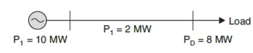
Penalty factor = \(L_n = \dfrac{1}{1-\dfrac{dP_L}{dP_n}}= \dfrac{1}{1-\dfrac{2}{10}}=\dfrac{10}{8}\)
- Cost of received power =\[= (0.1\times 10+3)\times \dfrac{10}{8} = \mathrm{Rs. 5/MWh}\]
Problem-3
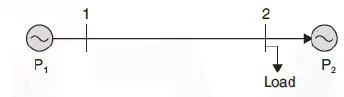
A two-bus system is shown in Fig. If a load of 125 MW is transmitted from plant 1 to the load, a loss of 15.625 MW is incurred. Determine the generation schedule and the load demand if the cost of received power is Rs. 24/MWhr. Solve the problem using coordination equations and the penalty factor method approach. The incremental production costs of the plants are
Solution-3
Since load is at Bus-2 alone, the loss in line will not be affected by Generator at Plant-2
- Hence,\[\begin{aligned} P_L & = B_{11}P_1^2 \qquad B_{12}=B_{21}=0~\text{and}~B_{22} = 0\\ 15.625 & = B_{11} \times 125^2 \Rightarrow B_{11} = 0.001 \end{aligned}\]
- Now, coordination equation:\[\begin{aligned} \dfrac{dF_1}{dP_1}+\lambda \dfrac{dP_L}{dP_1} & = \lambda \end{aligned}\]
Since, \(P_L=0.001P_1^2 \Rightarrow \dfrac{dP_L}{dP_1} = 0.002P_1\)
- Substituting in the coordination equation for plant\[\begin{aligned} & 0.025 P_{1}+15+\lambda 0.002 P_{1}=\lambda \\ \Rightarrow & 0.025 P_{1}+0.048 P_{1}+15=24 \\ \Rightarrow & 0.073 P_{1}=9 \\ \Rightarrow & P_{1}=123.28 \mathrm{MW} \end{aligned}\]
- The coordination equation for plant 2,\[\begin{gathered} 0.05 P_{2}+20=24 \\ \Rightarrow P_{2}=80 \mathrm{MW} . \end{gathered}\]
Transmission loss \(P_{L}=0.001 \times(123.28)^{2}=15.19 \mathrm{MW}\)
Load, \(P_{D}=123.28+80-15.19=188.1 \mathrm{MW}\).
- Penalty factor of Plant-1 is\[\begin{aligned} & \frac{1}{1-\frac{\partial P_{L}}{d P_{1}}}=\frac{1}{1-\left(0.002 P_{1}\right)} \\ & \frac{d F_{1}}{d P_{1}}\left(\frac{1}{1-0.002 P_{1}}\right)=24 \\ \Rightarrow & \frac{0.025 P_{1}+15}{1-0.002 P_{1}}=24 \\ \therefore & P_{1}=123.28 \mathrm{MW} \end{aligned}\]
Since \(\dfrac{dP_L}{dP_2}=0 \Rightarrow L_2 = \text{unity}\)
- The incremental cost of received power equals the incremental cost of production\[\begin{aligned} 0.05P_2+20& = 24\\ \Rightarrow P_2 & = 80~\mathrm{MW} \end{aligned}\]
Problem-4
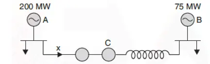
Two generating stations A and B have full load capacities of 200 MW and 75 MW respectively. The inter-connector connecting the two stations has an induction motor/synchronous generator (plant C) of full load capacity 25 MW. Percentage changes of speeds of A, B and C are 5, 4 and 3 respectively. The loads on bus bars A and B are 75 MW and 30 MW respectively. Determine the load taken by the set C and indicate the direction in which the energy is flowing.
Solution-4
Given data:
F.L. MW 200, 75, 25
% speed change 5, 4, & 3
Loads 75 MW and 30 MW
Assume that \(x\) MW is flowing from A to B
Load at station-A = \((75+x)\)
% drop in speed = \(\dfrac{5}{200}(75+x)\)
Load at station-B = \((30-x)\)
% drop in speed = \(\dfrac{4}{75}(30-x)\)
Since, the output of A corresponding to the power flow through the inter-connector is the input to C
Therefore, there is further reduction in frequency approximately by \(\dfrac{3x}{25}\)
- The total reduction in frequency from both A and C and the reduction of frequency from B when referred to Bus-B should be same\[\begin{aligned} & \dfrac{5}{200}(75+x)+\dfrac{3x}{25} = \dfrac{4}{75}(30-x) \\ & \Rightarrow x = -1.35~\mathrm{MW} \end{aligned}\]
Hence, 1.35 MW of power will flow from B to A
Problem-5
Two turbo-alternators rated for 110 MW and 210 MW have governor drop characteristics of 5 per cent from no load to full load. They are connected in parallel to share a load of 250 MW. Determine the load shared by each machine assuming free governor action.
Solution-5
Since two-machines are working in parallel, the % drop in frequency from both the machines due to different loadings must be same.
Let \(x\) be the power supplied by 110 MW unit.
The % drop in speed = \(\dfrac{5x}{110}\)
Similarly, % drop in speed of 210 MW unit will be \(\dfrac{5x}{210}(250-x)\)
- Then\[\begin{aligned} & \dfrac{5x}{100} = \dfrac{5x}{210}(250-x) \Rightarrow ~ x = 85.93~\mathrm{MW} \end{aligned}\]
Power shared by 210 MW unit is \((250-85.93)=164.07\) MW
Power supplied by 110 MW unit will be 85.93 MW