Problem-1
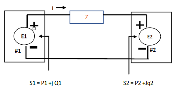
Two ideal voltage sources designated as machines 1 and 2 are connected, as shown in fig. If \(E_1= 100\angle 0^\circ ~ V, E_2=100\angle30^\circ~ V ~\text{and}~ Z=0+j5\) ohms, determine
whether each machine is generating or consuming real power and the amount
whether each machine is receiving or supplying reactive power and the amount , and
the P and Q absorbed by the impedance.
Solution-1
Machine 1 may be expected to be a generator because of the current direction and polarity markings. However , since P1 is positive and Q1 is negative, the machine consumes energy at the rate of 1000W and supplies reactive power of 268 VAR. the machine is actually a motor.
Machine 2, expected to be a motor, has negative P2 and negative Q2. Therefore, this machine generates energy at the rate of 1000W and supplies reactive power of 268 VAR. the machine is actually a generator.
Note that the supplied reactive power of 268+268= 536 VAR , which is required by the inductive reactance of 5ohm. Since the impedance is purely reactive, no P is consumed by the impedance, and all the watts generated by machine 2 are transferred to machine 1 .
Problem-2
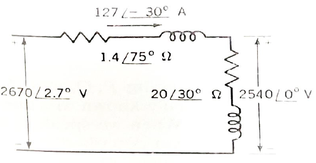
The terminal voltage of Y- connected load consisting of three equal impedances of \(20\angle 30^\circ\) ohms is 4.4 KV line to line. The impedance of each of three lines connecting the load to a bus at a sub station is \(Z_L= 1.4\angle 75^{\circ}\). Find the line-line voltage at the substation bus.
Solution-2
- The magnitude of the voltage to the neutral at the load is\[\begin{gathered} =\frac{4400}{\sqrt{3}} =2540 \mathrm{~V} \end{gathered}\]
- and , the voltage across the load, is chosen as reference If\[\begin{aligned} &I_{an}=\frac{2540 \angle 0 ^{\circ}}{20 \angle 30 ^{\circ}} =127.0 \angle-30^{\circ} \end{aligned}\]
- The line to neutral voltage at the substation is\[\begin{aligned} & V_{an}+\left(I_{an} . Z_{\mathrm{L}}\right)\\ &=2540 \angle 0^{\circ}+\left(127 \angle-30^{\circ} .14 \angle 75^{\circ}\right)\\ &=2540 \angle 0^{0}+177.8 \angle 45^{0}=2670 \angle 2.70^{\circ} \end{aligned}\]
the magnitude of the voltage at the substation bus is \(=\sqrt{3} * 2.67=4.62 \mathrm{KV}\)
Problem-3
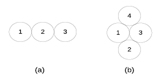
- Find the self GMD for each conductor configuration shown in
Figure. Radius of each conductor is 1 cm.
Solution-3
Problem-4
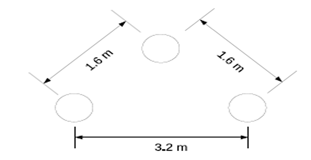
- Determine the inductance of a 3 phase line operating at 50 Hz and
conductors arranged as given in figure. The conductor diameter is 0.8
cm.
Solution-4
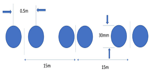
Problem-5
- A 500KV line has a bundling arrangement of two conductors per
phase as shown in fig. Compute the reactance per phase of this line at
50Hz. Each conductor carries 50% of the phase current . Assume full
transposition.
Solution-5
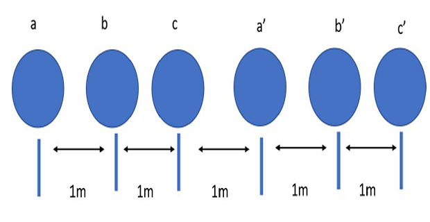
Problem-6
- A double circuit three phase line is shown in fig .The conductors
a,a’;b,b’; c,c’ belong to the same phase respectively.The radius of each
conductor is 1.5cm. Find the inductance of the double-circuit line in
mH/km/phase.
Solution-6
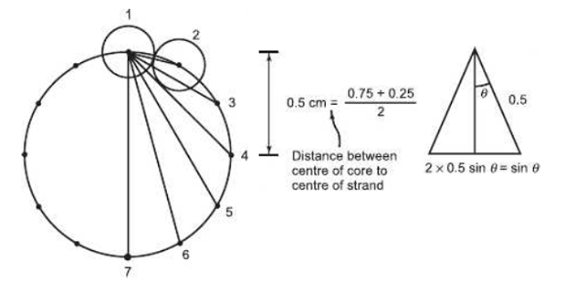
Problem-7
- Calculate the 50Hz inductive reactance at 1m spacing in ohms/km
of a cable consisting of 12 equal strands around a non conducting core.
The diameter of each strand is 0.25cm and the outside diameter of the
cable is 1.25cm.
Solution-7