Fault Current Computation Using Sequence networks
Demonstrate the use of sequence networks in the calculation of fault currents
- : (a) LG, (b) LL and (c) LLG fault occurs at bus-2 Find\[ \begin{aligned} \text{Generator}~ G & : 50~ MVA, 20 kV, X" = X_1 = X_2 = 20\%, ~X_0 = 7.5\% \\ \text{Motor}~ M & : 40~ MVA, 20 kV, X" = X_1 = X_2 = 20\%, ~X_0 = 10\%, Xn = 5\% \\ \text{Transformer}~ T_1 & : 50 MVA, 20~ kV ~\varDelta /110 ~kV~ Y,~ X = 10\% \\ \text{Transformer}~ T_2 & : 50 MVA, 20~ kV~ \varDelta /110~ kV ~Y,~ X = 10\% \\ \text{Transmission line} & : X_1 = X_2 = 24.2 ~\Omega, ~ X_0 = 60.5 ~\Omega \end{aligned} \]
Let us choose a base in the circuit of the generator. Then the per unit impedances of the generator are:
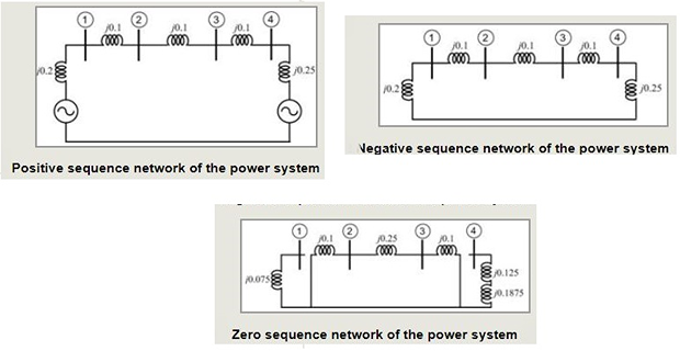
\[X_{G1} = X_{G2} = 0.2, ~~ X_{G0} = 0.075\]- the per unit impedances of the two transformers are\[X_{T1} = X_{T2} = 0.1\]
The MVA base of the motor is 40, while the base MVA of the total circuit is 50. Therefore the per unit impedances of the motor are
\[\begin{aligned} X_{M1} = X_{M2} = & 0.2 \times \dfrac{50}{40} = 0.25 \\ X_{M0} = & 0.1 \times \dfrac{50}{40} = 0.125 \\ X_n = & 0.05 \times \dfrac{50}{40} = 0.0625 \end{aligned}\]
- \[Z_{base} = \dfrac{110^2}{50} = 242~\Omega\]For the transmission line\[X_{L1} = X_{L2} = \dfrac{24.2}{242} = 0.1, ~~ X_{L0} = \dfrac{60.5}{242}= 0.25\]
Let us neglect the phase shift associated with the \(Y/ \varDelta\) transformers. Then the positive, negative and zero sequence networks are
- matrix for both positive and negative sequences we get the following\[Y_{bus1}=Y_{bus2}=j\left[\begin{array}{cccc} -15 & 10 & 0 & 0\\ 10 & -20 & 10 & 0\\ 0 & 10 & -20 & 10\\ 0 & 0 & 10 & 14 \end{array}\right]\]
- matrix Inverting the above matrix we get the following\[Z_{bus1}=Z_{bus2}=j\left[\begin{array}{cccc} 0.1467 & 0.1200 & 0.0933 & 0.0667\\ 0.1200 & 0.1800 & 0.1400 & 0.1000\\ 0.0933 & 0.1400 & 0.1867 & 0.1333\\ 0.0667 & 0.1000 & 0.1333 & 0.1667 \end{array}\right]\]
For the zero sequence
\[\begin{aligned} Y_{bus0}& =j\left[\begin{array}{cccc} -13.333 & 0 & 0 & 0\\ 0 & -14 & 4 & 0\\ 0 & 4 & -14 & 0\\ 0 & 0 & 0 & -3.2 \end{array}\right]\\ \Rightarrow Z_{bus0}&=j\left[\begin{array}{cccc} 0.075 & 0 & 0 & 0\\ 0 & 0.0778 & 0.0222 & 0\\ 0 & 0.0222 & 0.0778 & 0\\ 0 & 0 & 0 & 0.3125 \end{array}\right] \end{aligned}\]- For fault in bus-2, the Thevenin impedances\[Z_1 = Z_2 = j0.18, ~~ Z_0 = j0.0778\]
- Alternatively from Figure\[\begin{aligned} Z_1 = & Z_2 = j0.3 ~\parallel~ j0.45 = j0.18 \\ Z_0 = & j0.1 ~\parallel~ j0.35 = j0.0778 \end{aligned}\]
\(\bullet\)
- Let a bolted 1LG fault occurs at bus-2 when the system is unloaded with bus voltages being 1.0 per unit. Then\[I_{fa0} = I_{fa1} = I_{fa2} = \dfrac{1}{j\left(2\times 0.18 + 0.0778 \right)} = -j2.2841 ~pu\]
- Also,\[I_{fa}= 3I_{fa0} = -j6.8524~pu\]
- . We get the sequence components of the voltages as Also,\[\begin{aligned} V_{2a0} = & -j0.0778I_{fa0} = -0.1777\\ V_{2a1} = & 1-j0.18I_{fa1} = 0.5889\\ V_{2a2} = & -j0.18I_{fa2} = -0.4111\\ \end{aligned}\]
\(\bullet\)
- For a bolted LL fault, we can write\[I_{fa1} = -I{fa2} = \dfrac{1}{j2 \times 0.18} = -j2.7778 ~pu\]
- Then the fault currents are\[\left[\begin{array}{c} I_{fa}\\ I_{fb}\\ I_{fc} \end{array}\right]=C^{-1}\left[\begin{array}{c} 0\\ I_{fa1}\\ I_{fa2} \end{array}\right]=\left[\begin{array}{c} 0\\ -4.8113\\ 4.8113 \end{array}\right]\]
- Finally the sequence components of bus-2 voltages are\[\begin{aligned} V_{2a0} = & 0\\ V_{2a1} = & 1-j0.18 I_{fa1} = 0.5\\ V_{2a2} = & -j0.18 I_{fa2} = 0.5 \end{aligned}\]
- Therefore the voltages at the faulted bus are\[\left[\begin{array}{c} V_{a}\\ V_{b}\\ V_{c} \end{array}\right]=C^{-1}\left[\begin{array}{c} V_{2a0}\\ V_{2a1}\\ V_{2a2} \end{array}\right]=\left[\begin{array}{c} 1.0\\ -0.5\\ -0.5 \end{array}\right]\]
\(\bullet\)
- Let us assume that a bolted 2LG fault occurs at bus-2. Then,\[Z_{eq} = j0.18 \parallel j0.0778 = j0.0543\]
- The positive sequence current is\[I_{fa1} = \dfrac{1}{j0.18+Z_{eq}} = -j4.2676 ~pu\]
- The zero and negative sequence currents are then computed\[\begin{aligned} I_{fa0} = & -I_{fa1} \dfrac{j0.18}{j(0.18+0.0778)} = j2.9797~pu \\ I_{fa2} = & -I_{fa1} \dfrac{j0.0778}{j(0.18+0.0778)} = j1.2879~pu \end{aligned}\]
- Fault currents flowing in the line are\[\left[\begin{array}{c} I_{fa}\\ I_{fb}\\ I_{fc} \end{array}\right]=C^{-1}\left[\begin{array}{c} I_{fa0}\\ I_{fa1}\\ I_{fa2} \end{array}\right]=\left[\begin{array}{c} 0\\ 6.657\angle137.11^{0}\\ 6.657\angle42.89^{0} \end{array}\right]\]
- Sequence components of bus-2 voltages are\[\begin{aligned} V_{2a0} & =-j0.0778I_{fa0}=0.2318\\ V_{2a1} & =1-j0.18I_{fa1}=0.2318\\ V_{2a2} & =-j0.18I_{fa2}=0.2318 \end{aligned}\]
- Therefore the voltages at the faulted bus are\[\left[\begin{array}{c} V_{a}\\ V_{b}\\ V_{c} \end{array}\right]=C^{-1}\left[\begin{array}{c} V_{2a0}\\ V_{2a1}\\ V_{2a2} \end{array}\right]=\left[\begin{array}{c} 0.6954\\ 0\\ 0 \end{array}\right]\]
: assume that 2LG fault has occurred in bus-4 instead bus-2
- Then\[X_1 = X_2 = j0.1667, ~~X_0 = j0.3125\]
- We have\[Z_{eq} = j0.1667 \parallel j0.3125 = j0.1087\]
- Hence\[I_{fa1} = \dfrac{1}{j0.1667+Z_{}eq} = -j3.631~pu\]
- Also\[\begin{aligned} I_{fa0} & = -I_{fa1}\dfrac{j0.1667}{j(0.1667+0.3125)} = j1.2631~pu \\ I_{fa2} & = -I_{fa1} \dfrac{j0.3125}{j(0.1667+0.3125)} = j2.3678 ~pu \end{aligned}\]
- Therefore the fault currents flowing in the line are\[\left[\begin{array}{c} I_{fa}\\ I_{fb}\\ I_{fc} \end{array}\right]=C^{-1}\left[\begin{array}{c} I_{fa0}\\ I_{fa1}\\ I_{fa2} \end{array}\right]=\left[\begin{array}{c} 0\\ 5.5298\angle159.96^{0}\\ 5.5298\angle20.04^{0} \end{array}\right]\]
We shall now compute the currents contributed by the generator and the motor to the fault.
Let us denote the current flowing to the fault from the generator side by \(I_g\), while that flowing from the motor by \(I_m\).
Using the current divider principle, the positive sequence currents contributed by the two buses are
\[\begin{aligned} I_{ga1} & =I_{fa1}\times\dfrac{j0.25}{j0.75}=-j1.2103~pu\\ I_{ma1} & =I_{fa1}\times\dfrac{j0.5}{j0.75}=-j2.4206~pu \end{aligned}\]Similarly from Fig., the negative sequence currents are given as
\[\begin{aligned} I_{ga2} & =I_{fa2}\times\dfrac{j0.25}{j0.75}=-j0.7893~pu\\ I_{ma2} & =I_{fa2}\times\dfrac{j0.5}{j0.75}=-j1.5786~pu \end{aligned}\]
- Finally zero sequence current flowing from the generator to the fault is 0. Then we have\[\begin{aligned} I_{ga0} & = 0\\ I_{ma0} & = j1.2631~pu \end{aligned}\]
- Therefore the fault currents flowing from the generator side are\[\left[\begin{array}{c} I_{ga}\\ I_{gb}\\ I_{gc} \end{array}\right]=C^{-1}\left[\begin{array}{c} I_{ga0}\\ I_{ga1}\\ I_{ga2} \end{array}\right]=\left[\begin{array}{c} 0.4210\angle-90^0\\ 1.7445\angle173.07^{0}\\ 1.7445\angle6.93^{0} \end{array}\right]\]
- and those flowing from the motor are\[\left[\begin{array}{c} I_{ma}\\ I_{mb}\\ I_{mc} \end{array}\right]=C^{-1}\left[\begin{array}{c} I_{ma0}\\ I_{ma1}\\ I_{ma2} \end{array}\right]=\left[\begin{array}{c} 0.4210\angle90^0\\ 3.8512\angle154.07^{0}\\ 3.8512\angle25.93^{0} \end{array}\right]\]
It can be easily verified \(I_g + I_m = I_f\)