Bundled Conductors in Transmission Lines
Demonstrative Video
What are Bundled Conductors?
TL often instead of a single conductor per phase multiple conductors per phase are used.
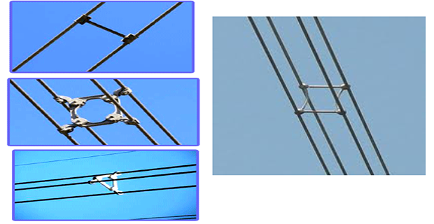
A metallic structure called spacers groups the conductors of a phase.
Spacers
maintain a constant distance between the conductors throughout their length
avoid clashing of conductors amongst themselves
connect them in parallel
Each phase can have two, three, or four conductors
Each conductor joined by the spacer belongs to the same phase
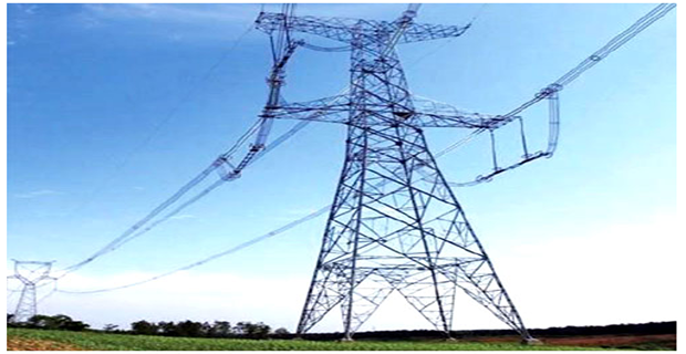
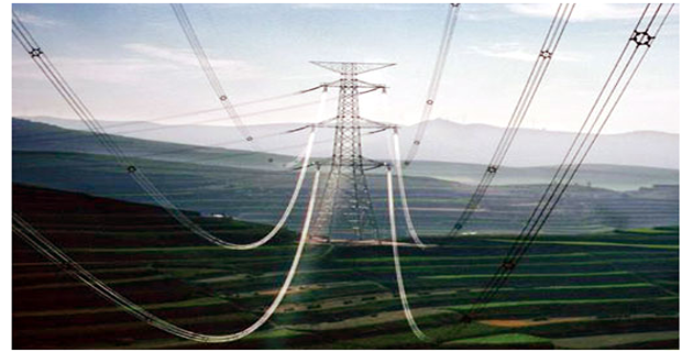
Three such group of conductors form a single circuit transmission or six such groups form double circuit transmission.
Bundled conductors with spacers

Single Circuit TL with Bundled Conductors

Double Circuit TL with Bundled Conductors

Inductance for Bundled Conductors
EHV line above 230 kV, corona loss and interference with communication circuit is excessive if there is one conductor per phase
Bundled conductor: two or more conductors in close proximity compared with spacing between phases
\(\Longrightarrow\) reduce the high voltage gradient at the conductor
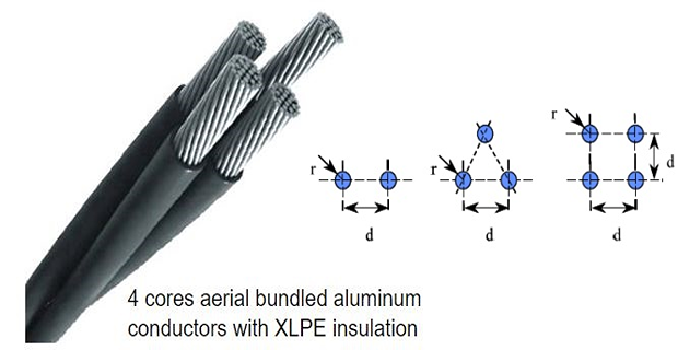
Bundled arrangements
Bundle consists of 2, 3, or 4 conductors.
The reduction of reactance is another advantage of bundling.
\(\Longrightarrow\) results from the increase GMR of the bundleThe GMR calculation for 2, 3, and 4 bundled conductors \[\begin{aligned} D_{s}^{b} & =\sqrt[4]{\left(D_{s}\times d\right)^2}=\sqrt{D_{s}\times d} \cdots \cdots 2-\mbox{conductor}\\ & =\sqrt[9]{\left(D_{s}\times d\times d\right)^{3}}=\sqrt[3]{D_{s}\times d^{2}}\cdots \cdots 3-\mbox{conductor}\\ & =\sqrt[16]{\left(D_{s}\times d\times d\times\sqrt{2}d\right)^{4}}=1.09\sqrt[4]{D_{s}\times d^{3}}\cdots 4-\mbox{conductor} \end{aligned}\]
Hence as we increase the number of conductors the GMR increases and hence \(L\) decrease.
Advantage of reducing Inductance of the line
The maximum power transfer capability of the line increases \[P = \left(\dfrac{Vs \cdot V_r}{X_L}\right) \cdot \sin\delta\]
reactance of conductors decreases, so reduced voltage drop in conductors, so voltage regulation improves (decreases).
Advantages of Bundled Conductors
\(\Rightarrow\) primarily employed to reduce the corona loss and radio interference. However they have several advantages:
reduces the voltage gradient in the vicinity of the line \(\Rightarrow\) reduces possibility of corona discharge \(\Rightarrow\) transmission efficiency \(\uparrow\)
Bundled conductor lines will have higher capacitance to neutral in comparison with single lines \(\Rightarrow\) will have higher charging currents \(\Rightarrow\) helps in improving the power factor.
higher \(C\) and lower \(L\) than ordinary lines \(\Rightarrow\) higher SIL \(\left(Z_c=\sqrt{\dfrac{L}{C}}\right)\) \(\Rightarrow\) will have higher maximum power transfer ability.
\(\uparrow\) self GMD or GMR inductance per phase will be reduced compared to single conductor line \(\Rightarrow\) \(X_L\) per phase \(\downarrow\) compared to ordinary single line \(\Rightarrow\) lesser loss due to reactance drop.
The ampacity i.e. current carrying capacity of bundled conductors is much increased in comparison to single large conductor owing to reduced skin effect.
As the bundled conductors have more effective surface area exposed to air, it has better and efficient cooling and hence better performance compared to a single conductor.