Master Circuit Analysis with Transfer Functions
Demonstrative Video
Transfer Function
TF is a key concept in signal processing as it indicates how the signal is processed as it passes through the network
Vital tool used for numerous circuit analysis
fitting tool for finding network response
determining or designing network stability
used for network synthesis
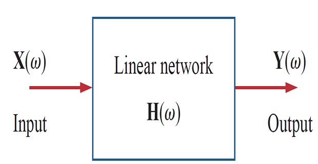
TF of a network describes how the output behaves w.r.t the input
It specifies the transfer from the input to the output in the s-domain, assuming no initial energy
Definition: The TF \(H(s)\) is the ratio of the output response \(Y(s)\) to the input excitation \(X(s)\), assuming all initial conditions are zero.
\[\boxed{H(s) =
\dfrac{Y(s)}{X(s)}}\]

The input and output can be either current or voltage at any place in the circuit
There are four possible transfer functions: \[\begin{aligned} H(s)&= \color{magenta}{\textbf{Voltage gain}}=\frac{V_{o}(s)}{V_{i}(s)} \\ H(s)&= \color{blue}{\textbf{Current gain }}=\frac{I_{o}(s)}{I_{i}(s)} \\ H(s)&= \color{red}{\textbf{Impedance }}=\frac{V(s)}{I(s)} \\ H(s)&=\color{purple}{\textbf{Admittance }}=\frac{I(s)}{V(s)} \end{aligned}\]
\(H(s)\) is dimensionless
TF in Circuit Analysis
\[\begin{aligned} Y(s) & = H(s) \cdot X(s) \\ \text{Special case : }~x(t) & = \delta(t)~ \Leftarrow ~ \text{Unit impulse function}\\ \Rightarrow ~ X(s) & = 1\\ \Rightarrow ~ Y(s) & = H(s) ~ \quad ~ \Rightarrow \boxed{y(t) = h(t) = \mathcal{L}^{-1}[H(s)]} \end{aligned}\]
\(h(t)\) represents the unit impulse response - Time domain response of the network to a unit impulse.
Once we know \(h(t)\) of a network, we can obtain the response of the network to any input signal
Problem
The output of a linear system is \(y(t) = 10e^{-t}\cos 4t u(t)\) when the input is \(x(t) = e^{-t}u(t)\). Determine the transfer function and the impulse response of the system ?
Solution :
\[\begin{aligned} x(t) & = e^{-t}u(t) \quad \Rightarrow X(s) = \dfrac{1}{s+1}\\ y(t) & = 10e^{-t} \cos 4t u(t) \quad \Rightarrow Y(s) = \dfrac{10(s+1)}{(s+1)^2+4^2} \\ H(s) & = \dfrac{Y(s)}{X(s)} = \dfrac{10(s^2+2s+1)}{s^2+2s+17} \\ \Rightarrow~h(t) & = 10\delta(t)-40e^{-t}\sin 4t u(t) \end{aligned}\]
Problem
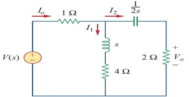
Find the transfer function \(H(s) = V_0(s)/I_0(s)\) of the circuit ?

Solution: \[\begin{gathered} I_{2}=\frac{(s+4) I_{o}}{s+4+2+1 / 2 s} \\ V_{o}=2 I_{2}=\frac{2(s+4) I_{o}}{s+6+1 / 2 s} \\ H(s)=\frac{V_{o}(s)}{I_{o}(s)}=\frac{4 s(s+4)}{2 s^{2}+12 s+1} \end{gathered}\]
Poles and Zeros of the TF
TF can be represented as \[\begin{aligned} \mathbf{F}(s)&=\frac{\mathbf{N}(s)}{\mathbf{D}(s)}=\frac{a_{m} s^{m}+a_{m-1} s^{m-1}+\cdots+a_{1} s+a_{0}}{b_{n} s^{n}+b_{n-1} s^{n-1}+\cdots+b_{1} s+b_{0}} \\ & = \dfrac{K(s-Z_1)(s-Z_2) \cdots (s-Z_{m-1})(s-Z_m)}{(s-P_1)(s-P_2) \cdots (s-P_{n-1})(s-P_n)} \end{aligned}\]
\(K = a_m/b_n\)
Roots of \(\mathbf{N(s)}=0\) are called the zeros of TF as they make TF = 0
Roots of \(\mathbf{D(s)}=0\) are called the poles of TF as they cause TF \(\rightarrow~\infty\)
Properties:
If the poles and zeros are not repeated, they are called simple poles and simple zeros, otherwise they are called multiple poles and multiple zeros.
All poles and zeros, if complex, must occur in conjugate pairs.
The real parts of all poles must be negative and any pole on the \(j\omega\)-axis must be simple.
S-plane
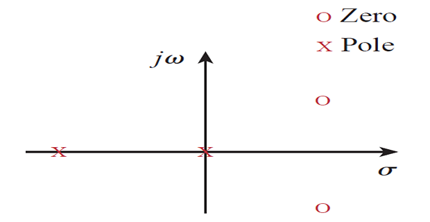
The zeros and poles are often located in the s-plane

The location of the roots in the s-plane provides an insight into the nature of the network function and this information is used in network analysis and synthesis.
Problem
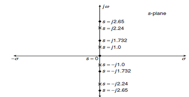
Draw the pole-zero diagram of the impedance transformed function \[Z(s)=\frac{s\left(s^{2}+3\right)\left(s^{2}+7\right)}{\left(s^{2}+1\right)\left(s^{2}+5\right)}\]
Solution:
For poles, denominator \(=0\) \[\begin{aligned} & \left(s^{2}+1\right)\left(s^{2}+5\right)=0 \\ & s^{2}=-1 \quad s^{2}=-5 \\ & s=\pm j \quad s=\pm j \sqrt{5} \\ & s=\pm j \quad \pm j 2.24 \end{aligned}\] For zeros, numerator \(=0\) \[\begin{aligned} & s\left(s^{2}+3\right)\left(s^{2}+7\right)=0 \\ & s=0, s^{2}=-3 \quad s^{2}=-7 \\ & s=0, \quad s=\pm j \sqrt{3} \quad s=\pm j \sqrt{7} \\ & s=0 \quad \pm j 1.732 \quad \pm j 2.65 \end{aligned}\]
