Fundamentals of Inductors
Demonstrative Video
Inductors
An inductor is a passive element designed to store energy in its magnetic field.
Inductors find numerous applications in electronic and power systems.
They are used in power supplies, transformers, radios, TVs, radars, and electric motors.
Any conductor of electric current has inductive properties and may be regarded as an inductor.
But in order to enhance the inductive effect, a practical inductor is usually formed into a cylindrical coil with many turns of conducting wire.
An inductor is usually constructed by coiling a wire around some type of form (core).
Current flowing through the coil creates a magnetic field or flux that links the coil and core.
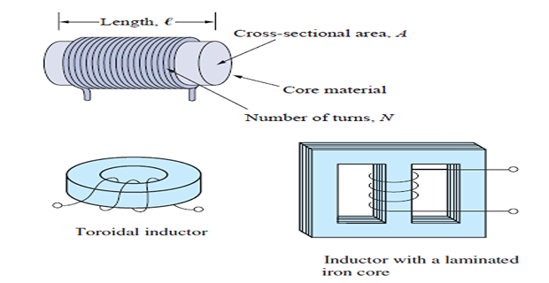
The inductance of an inductor depends on its physical dimension and construction.
Formulas for calculating the inductance of inductors of different shapes are derived from electromagnetic theory and can be found in standard electrical engineering handbooks.
For example, for the inductor, (solenoid) \[L=\frac{N^{2} \mu A}{\ell}\] where \(N\) is the number of turns, \(\ell\) is the length, \(A\) is the cross-sectional area, and \(\mu\) is the permeability of the core.
We can see from Eq. that inductance can be increased by increasing the number of turns of coil, using material with higher permeability as the core, increasing the cross-sectional area, or reducing the length of the coil.
Principle
When \(i(t)\) changes in value, the resulting \(\Phi\) changes.
According to Faraday’s law of electromagnetic induction, time-varying magnetic flux linking a coil induces voltage across the coil.
For an ideal \(L\), the voltage is proportional to the time rate of change of the current.
The polarity of the voltage is such as to oppose the change in current.
The constant of proportionality is called inductance (\(L\)).
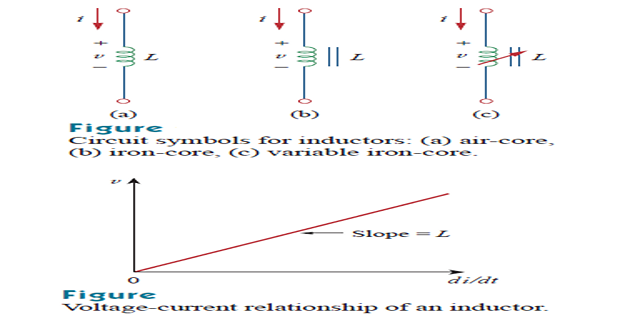
The voltage and current are related by: \[v(t) = L\cdot \dfrac{di}{dt}\]
Unit henries (H), which are equivalent to volt seconds per ampere.
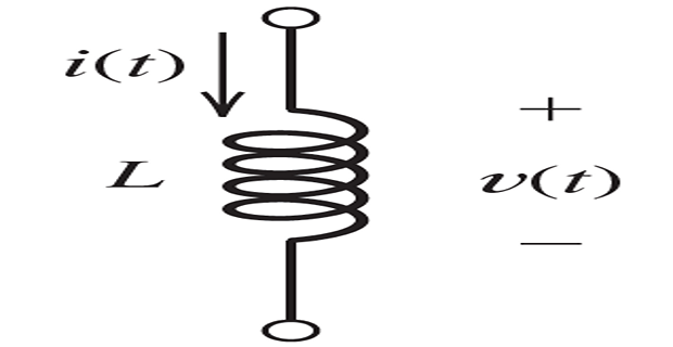
Typically, inductances ranges from \(\mu\)H to mH
Fluid-Flow Analogy
The fluid-flow analogy for inductance is the inertia of the fluid flowing through a frictionless pipe of constant diameter.
The pressure differential between the ends of the pipe is analogous to voltage, and the flow rate or velocity is analogous to current.
Thus, the acceleration of the fluid is analogous to rate of change of current.
A pressure differential exists between the ends of the pipe only when the flow rate is increasing or decreasing.
One place where the inertia of flowing fluid is encountered is when a valve closes suddenly, cutting off the flow.
Current in Terms of Voltage
Suppose that we know the initial current \(i(t_0)\) and the voltage \(v(t)\) across an inductance.
Furthermore, suppose that we need to compute the current for \(t > t_0\)
\[\begin{aligned} v(t) &=L \frac{d i}{d t} \\ d i &=\frac{1}{L} v(t) d t \\ \int_{i\left(t_{0}\right)}^{i(t)} d i &=\frac{1}{L} \int_{t_{0}}^{t} v(t) d t \\ i(t) &=\frac{1}{L} \int_{t_{0}}^{t} v(t) d t+i\left(t_{0}\right) \end{aligned}\]
as long as \(v(t)\) is finite, \(i(t)\) can change only by an incremental amount in a time increment.
Thus, \(i(t)\) must be continuous with no instantaneous jumps in value (i.e., discontinuities).
Stored Energy
\[\begin{aligned} p(t) &=v(t) i(t) \\ p(t) &=L i(t) \frac{d i}{d t} \\ w(t) &=\int_{t_{0}}^{t} p(t) d t \\ w(t) &=\int_{t_{0}}^{t} L i \frac{d i}{d t} d t \\ w(t) &=\int_{0}^{i(t)} L i d i \\ w(t) &=\frac{1}{2} L i^{2}(t) \end{aligned}\]
This represents energy stored in the inductance that is returned to the circuit if the current changes back to zero.
Inductances In Series and Parallel
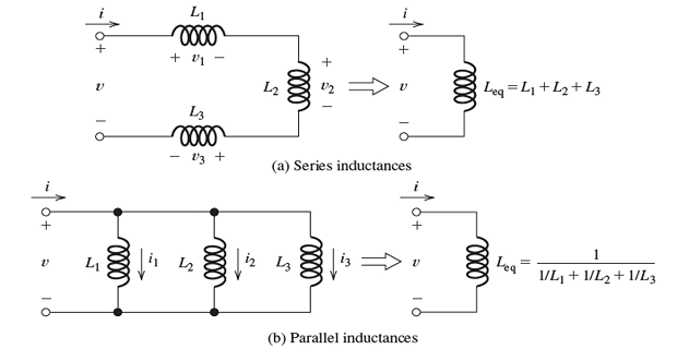
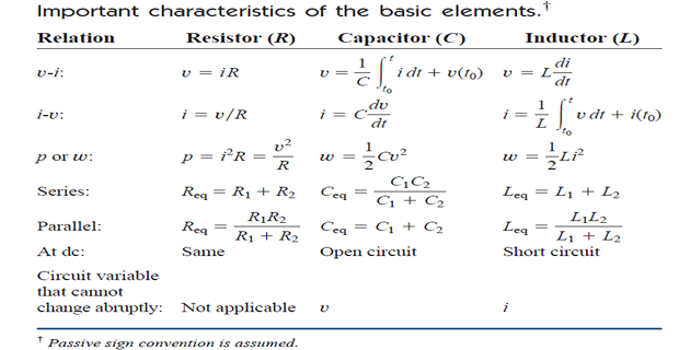
Notice that inductances are combined in exactly the same way as are resistances.
Parasitic Effects for Real Inductors
Real inductors have parasitic effects in addition to the desired inductance

The series resistance \(R_s\) is caused by the resistivity of the material composing the wire.
The parallel capacitance is associated with the electric field in the dielectric (insulation) between the coils of wire. It is called inter-winding capacitance.
The parallel resistance \(R_p\) represents core loss due, in part, to eddy currents in the core
Important properties of an inductor
the voltage across an inductor is zero when the current is constant. \[\text{An inductor acts like a short circuit to dc}\]
The current through an inductor cannot change instantaneously
Like the ideal capacitor, the ideal inductor does not dissipate energy. The energy stored in it can be retrieved at a later time. The inductor takes power from the circuit when storing energy and delivers power to the circuit when returning previously stored energy.
A practical, non-ideal inductor has parasitic effect causing losses
