Demonstrative Video
Kirchhoff’s Laws
Laws are more comprehensive than Ohm’s law and are used for solving electrical networks which may not be readily solved by the latter.
Kirchhoff’s laws:
Kirchhoff’s Point Law or Current Law (KCL)
Kirchhoff’s Mesh Law or Voltage Law (KVL)
particularly useful:
in determining the equivalent resistance of a complicated network of conductors
for calculating the currents flowing in the various conductors.
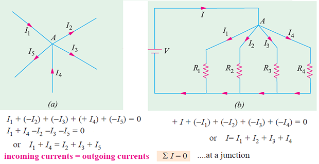
Kirchhoff’s Current Law (KCL)
In any electrical network, the algebraic sum of the currents meeting at a point (or junction) is zero.
It simply means that the total current leaving a junction is equal to the total current entering that junction.
Based on the law of conservation of charge which requires that the algebraic sum of charges within a system cannot change.
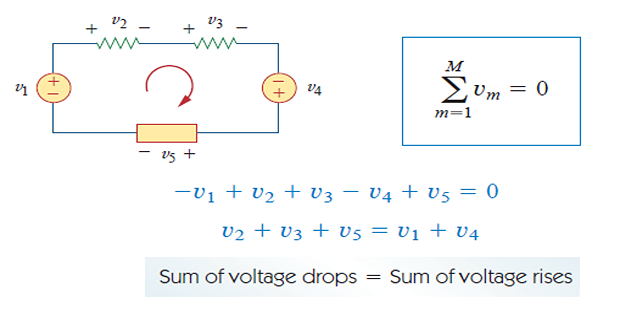
Kirchhoff’s Voltage Law (KVL)
The algebraic sum of all voltages around a closed path (or loop) is zero.
Based on the principle of conservation of energy:
Resistances in Series and Parallel
How to replace series or parallel combinations of resistances by equivalent resistances?
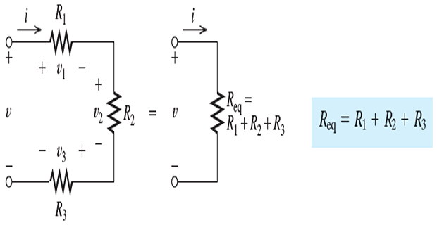
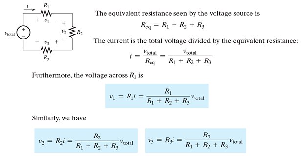
Series Resistances
In a series circuit the elements are connected end to end and that the same current flows through all of the elements
- By Ohm’s law, we can write:\[\begin{aligned} v_1 & = R_1i \\ v_2 & = R_2i \\ v_3 & = R_3i \end{aligned}\]
- Using KVL, we can write:\[\begin{aligned} v &= v_1+v_2+v_3\\ & = R_1i+R_2i+R_3i\\ & = (R_1+R_2+R_3)i\\ & = R_{eq}i \end{aligned}\]
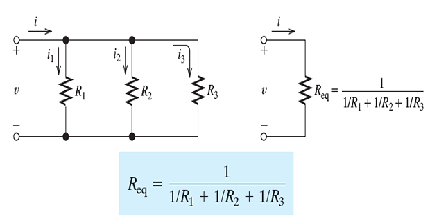
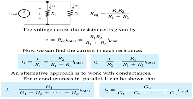
Parallel Resistances
In a parallel circuit, the voltage across each element is the same
- Applying Ohm’s law:\[\begin{aligned} &i_{1}=\frac{v}{R_{1}} \\ &i_{2}=\frac{v}{R_{2}} \\ &i_{3}=\frac{v}{R_{3}} \end{aligned}\]
- apply KCL to the top node of the circuit:\[\begin{aligned} &i=i_{1}+i_{2}+i_{3} \\ &i=\frac{v}{R_{1}}+\frac{v}{R_{2}}+\frac{v}{R_{3}} \\ &i=\left(\frac{1}{R_{1}}+\frac{1}{R_{2}}+\frac{1}{R_{3}}\right) v \end{aligned}\]
- if four resistances are in parallel, the equivalent resistance is\[R_{\mathrm{eq}}=\frac{1}{1 / R_{1}+1 / R_{2}+1 / R_{3}+1 / R_{4}}\]
- Similarly, for two resistances, we have\[\begin{aligned} &R_{\mathrm{eq}}=\frac{1}{1 / R_{1}+1 / R_{2}} \\ &R_{\mathrm{eq}}=\frac{R_{1} R_{2}}{R_{1}+R_{2}} \end{aligned}\]
Sometimes, resistive circuits can be reduced to a single equivalent resistance by repeatedly combining resistances that are in series or parallel.
Conductances in Series and Parallel
Recall that conductance is the reciprocal of resistance
- elements For a series combination of\[G_{\mathrm{eq}}=\frac{1}{1 / G_{1}+1 / G_{2}+\cdots+1 / G_{n}}\]
Conductances in series combine as do resistances in parallel.
- For two conductances in series, we have:\[G_{\mathrm{eq}}=\frac{G_{1} G_{2}}{G_{1}+G_{2}}\]
- conductances in parallel For\[G_{\mathrm{eq}}=G_{1}+G_{2}+\cdots+G_{n}\]
Conductances in parallel combine as do resistances in series
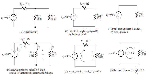
Circuit Analysis Using Series/Parallel Equivalents
Network analysis is the process of determining the current, voltage, and power for each element, given the circuit diagram and the element values
Steps in solving circuits using series/parallel equivalents
Begin by locating a combination of resistances that are in series or parallel. Often the place to start is farthest from the source.
Redraw the circuit with the equivalent resistance for the combination found in step 1.
Repeat steps 1 and 2 until the circuit is reduced as far as possible. Often (but not always) we end up with a single source and a single resistance.
Solve for the currents and voltages in the final equivalent circuit. Then, transfer results back one step and solve for additional unknown currents and voltages. Again transfer the results back one step and solve. Repeat until all of the currents and voltages are known in the original circuit.
Check your results to make sure that KCL is satisfied at each node, KVL is satisfied for each loop, and the powers add to zero.
Example of series/parallel operation
Voltage Divider and Current Divider Circuits
Voltage Division: When a voltage is applied to a series combination of resistances, a fraction of the voltage appears across each of the resistances
Current Division: The total current flowing into a parallel combination of resistances divides, and a fraction of the total current flows through each resistance
Star-Delta Transformations
Identifying parallel and series combinations of resistors can often lead to a significant reduction in the complexity of a circuit.
In situations where such combinations do not exist, star-delta conversion proved to be useful.

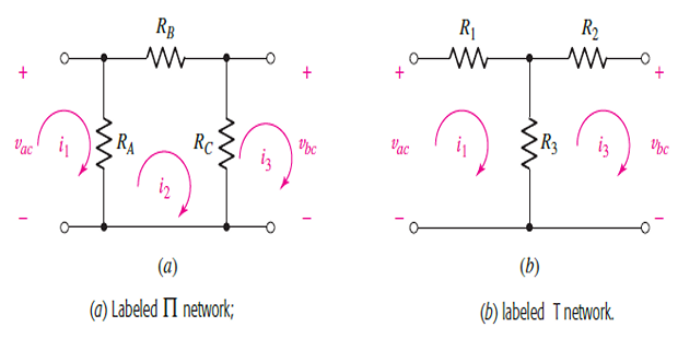
KVL for \(\Pi\)-network
KVL for T-network
- and substituting Remove\[\begin{aligned} \left(R_{A}-\frac{R_{A}^{2}}{R_{A}+R_{B}+R_{C}}\right) i_{1}-\frac{R_{A} R_{C}}{R_{A}+R_{B}+R_{C}} i_{3}&=v_{a c}\\ -\frac{R_{A} R_{C}}{R_{A}+R_{B}+R_{C}} i_{1}+\left(R_{C}-\frac{R_{C}^{2}}{R_{A}+R_{B}+R_{C}}\right) i_{3}&=-v_{b c} \end{aligned}\]
- Comparing terms\[R_{3}=\frac{R_{A} R_{C}}{R_{A}+R_{B}+R_{C}}\]
- Star to Delta Conversion\[\begin{aligned} &R_{A}=\frac{R_{1} R_{2}+R_{2} R_{3}+R_{3} R_{1}}{R_{2}} \\ &R_{B}=\frac{R_{1} R_{2}+R_{2} R_{3}+R_{3} R_{1}}{R_{3}} \\ &R_{C}=\frac{R_{1} R_{2}+R_{2} R_{3}+R_{3} R_{1}}{R_{1}} \end{aligned}\]
- Delta to Star Network\[\begin{aligned} R_{1} &=\frac{R_{A} R_{B}}{R_{A}+R_{B}+R_{C}} \\ R_{2} &=\frac{R_{B} R_{C}}{R_{A}+R_{B}+R_{C}} \\ R_{3} &=\frac{R_{C} R_{A}}{R_{A}+R_{B}+R_{C}} \end{aligned}\]